Implementation
This section covers the mechanical design of the finger and gripper, the electronics, and the software used to drive the system.
Mechanical
Finger Design
Each finger contains two voice coil actuators (VCAs) whose motion is coupled to a single 2-DoF output surface through a pair of pinned links. The figure below shows (A) a photo with the front cover removed, (B) an annotated view of the key internal components, and (C) a front view showing the linear encoder scale mounted to the coil-bearing block attachment.
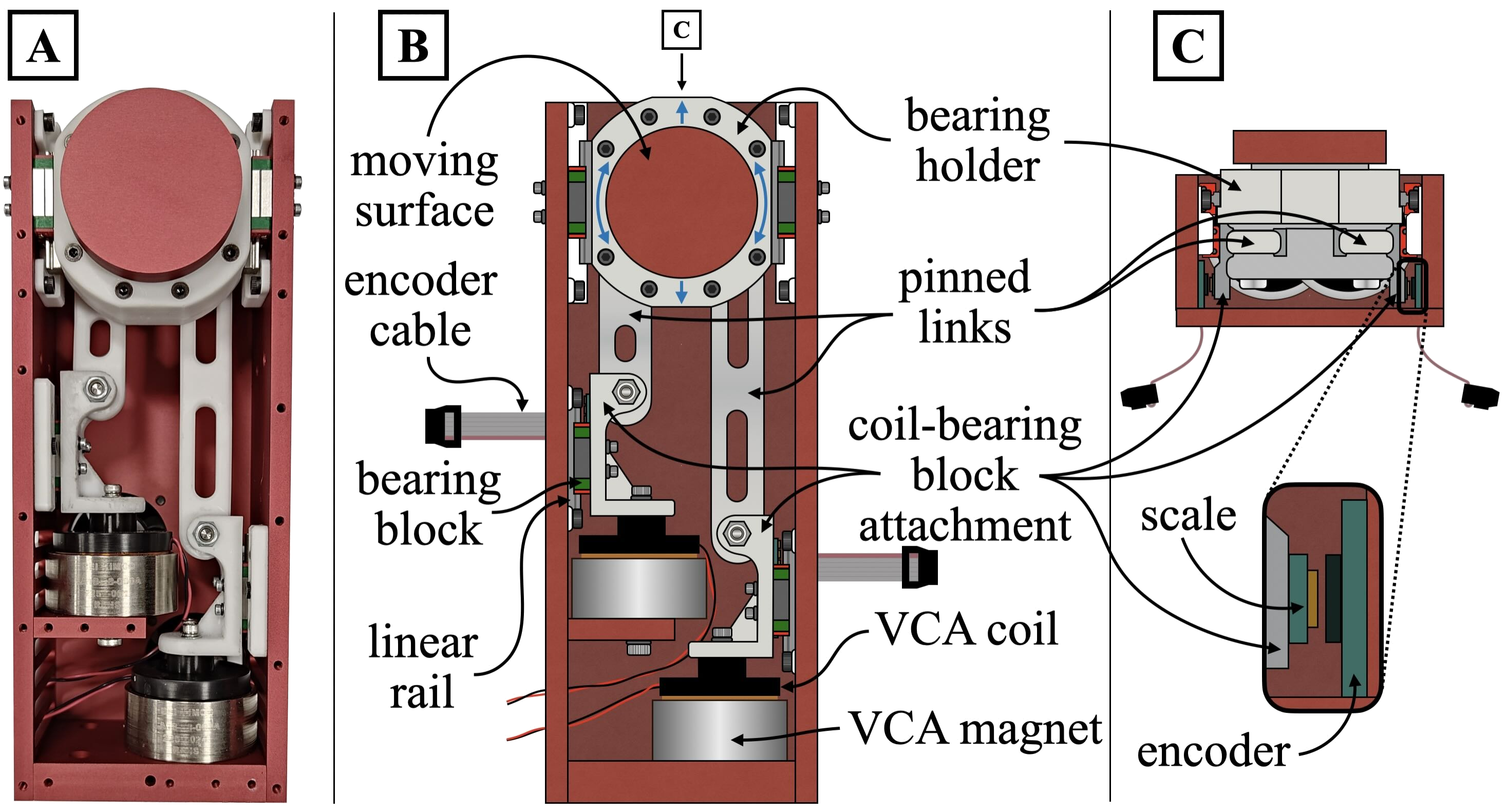
We selected the LA18-18-000A VCA from BEI Kimco for its high peak acceleration — with a peak force of 48.93 N and a moving coil mass of 0.047 kg, the theoretical peak acceleration is roughly 100$g$. Each VCA’s moving coil is attached to a very-light-preload Hiwin MGN07 bearing block sliding on a lubricated rail, which trades rigidity for low friction. The two coils in a finger are mechanically coupled to the output surface through links pinned at both ends with titanium shoulder screws and ceramic ball-bearings, minimizing mass and friction. When the two coils move in phase, the output surface translates linearly. When they move 180° out of phase, the output surface rotates about its normal. Superimposing the two motions yields 2-DoF output. Non-contact Posic linear encoders (5 µm resolution) mounted on each coil-bearing block attachment provide position feedback for the 40 kHz PD control loop.
The custom parts are anodized aluminum (red), PLA (white), and White V5 resin (off-white). Fans on the back of the finger cool the VCA magnets and coils through cutouts in the frame.
Gripper Assembly and Cable Drive
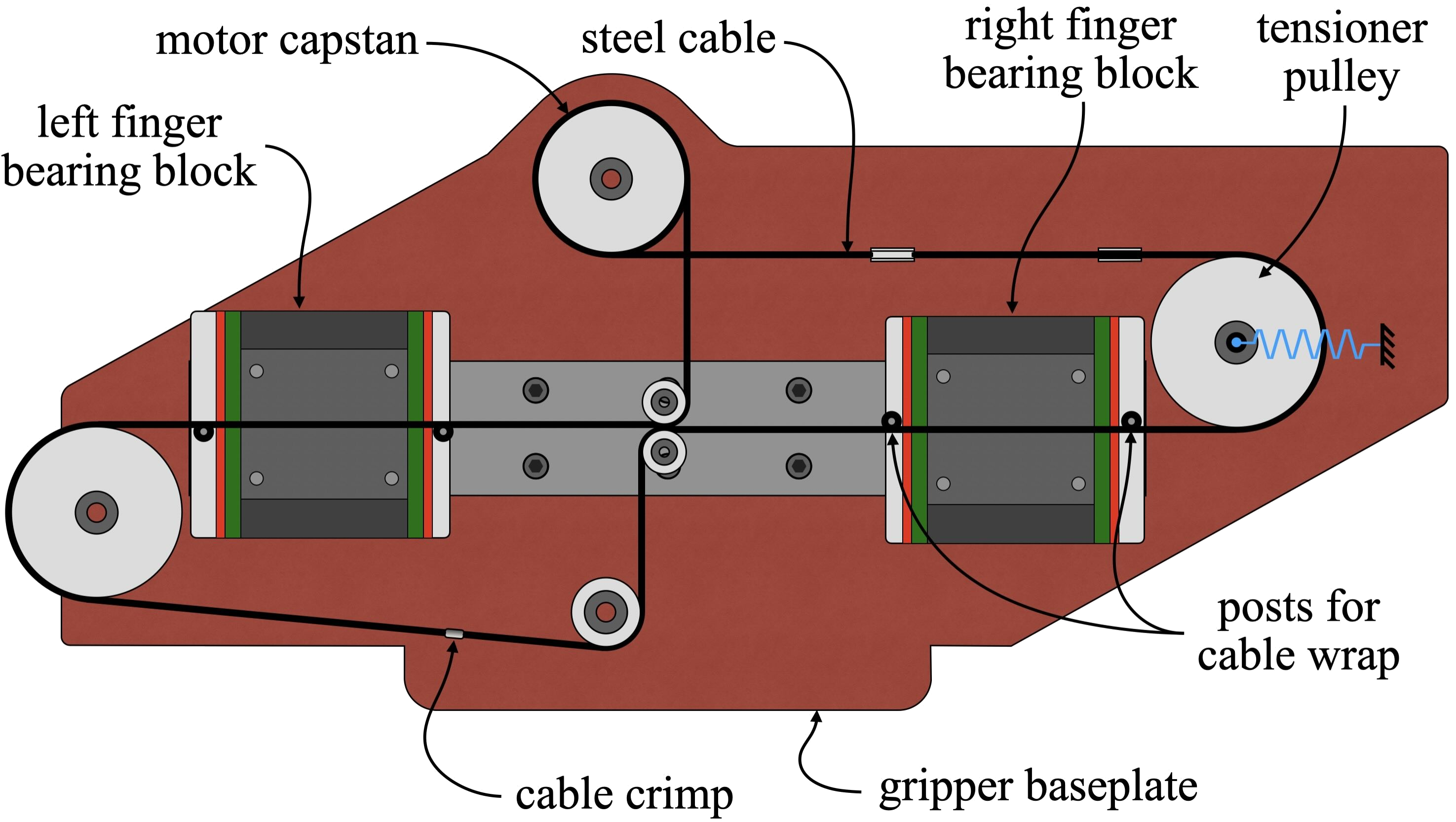
Two fingers were mounted to the same 42 mm wide Hiwin MGWR15 rail using large, low-friction MGW15 bearing blocks. The wide rail and bearing block combination was selected for its large static and dynamic moment ratings, necessary to handle loads from the cantilevered contact surface. The grasping motion is driven by a single 150 W Maxon motor via a cable drive: a steel cable wraps around a motor capstan and connects to both finger bearing blocks via crimp terminations and a tensioner pulley, so that rotating the motor opens or closes the gripper symmetrically.
The finger surfaces were aligned by placing a 123 block between the moving surfaces, clamping the fingers, and progressively tightening the mounting screws.
CAD
Interactive CAD coming soon.
Key Components
Key Components (Table I from paper)
| Component | Manufacturer | Part # |
|---|---|---|
| Voice Coil Actuator | BEI Kimco | LA18-18-000A |
| Bearing Block (VCA) | Hiwin | MGN07CZ0H |
| Rail (VCA) | Hiwin | MGNR07R |
| Motor Driver | Pololu | H2 |
| Linear Encoder | Posic | ID4501L |
| Encoder Scale | Posic | TPLS04-026 |
| Polyurethane Sheet | McMaster | 8716K61 |
| Rail (Finger) | Hiwin | MGWR15R |
| Bearing Block (Finger) | Hiwin | MGW15HZ0HM |
| Motor (Gripper) | Maxon | 148877 |
Note: The gray cast iron output surface used in the transport experiments was replaced with an aluminum disk with a 1/16”-thick polyurethane sheet affixed using cyanoacrylate for the gripper demos.
Electrical
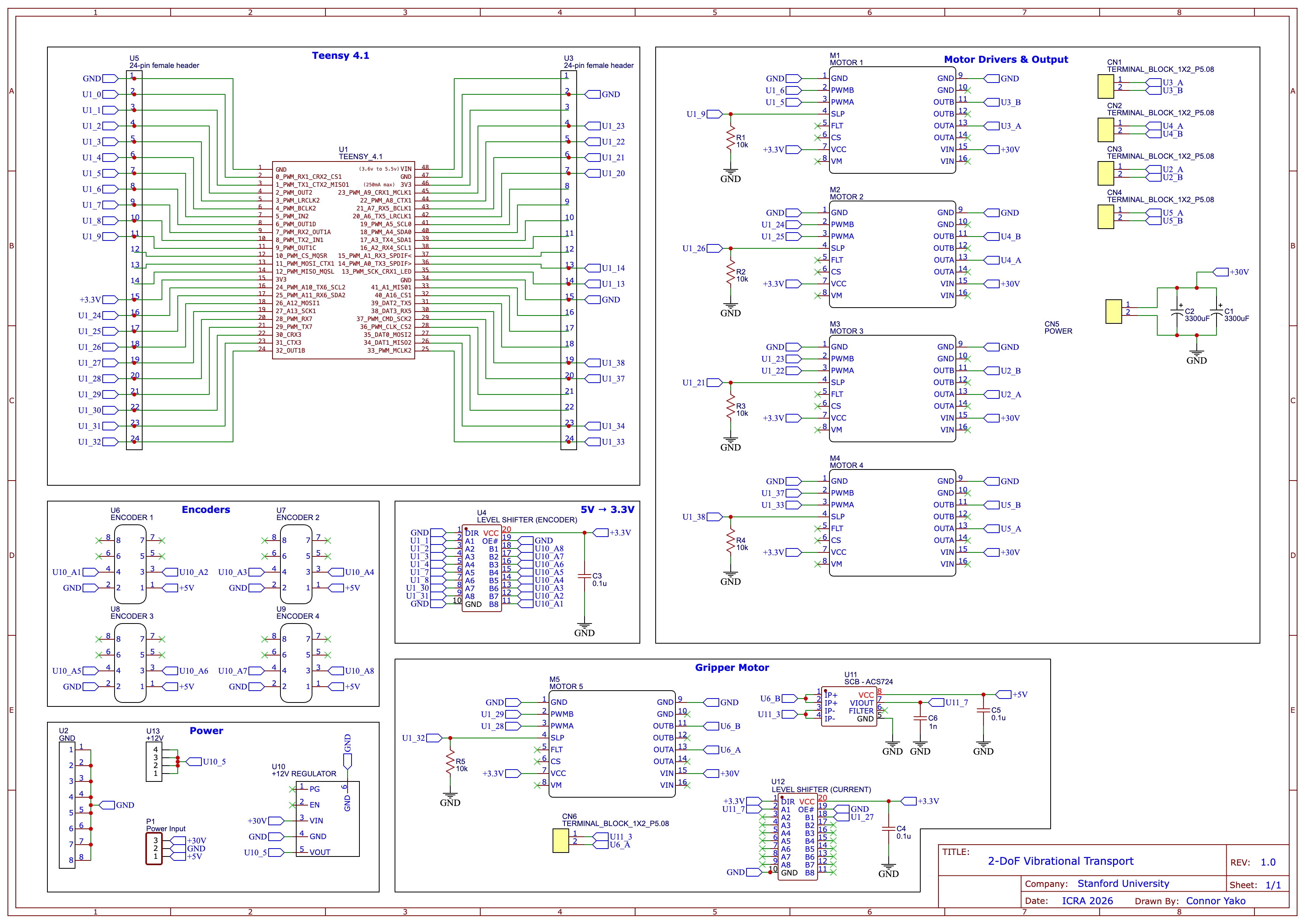
Each finger contains four LA18-18-000A VCAs (two per finger × two fingers), each driven by a Pololu H2 PWM motor driver powered at 30 V. Position feedback for each VCA is provided by a Posic linear encoder outputting A/B pulses at 1 MHz with 5 µm resolution. Because these encoders output 5 V logic and the Teensy 4.1 is a 3.3 V device, a level shifter (SN74LVC245A) is used to translate all four encoder signals. The Teensy’s hardware quadrature encoder pins handle the high-frequency pulse counting, and the PWM output pins drive the Pololu motor drivers.
The gripper motor (Maxon) is driven by a fifth Pololu H2 motor driver, with an ACS724 current sensor providing closed-loop current feedback for normal force control. A 12 V regulator (from the 30 V supply) powers auxiliary logic. All motor driver outputs are brought out to terminal blocks for easy connection to the finger cables.
Schematic
The full circuit schematic is shown below and available as a PDF here.
Electrical Components
| Component | Quantity | Description |
|---|---|---|
| Teensy 4.1 | 1 | Microcontroller; hardware quadrature encoder pins and FlexPWM timers |
| Pololu H2 motor driver | 5 | PWM motor driver (4× VCA + 1× gripper motor); 30 V supply, up to 11 A continuous |
| Posic linear encoder + scale (ID4501L / TPLS04-026) | 4 | Non-contact encoder, 5 µm resolution, 1 MHz output |
| Level shifter (SN74LVC245A) | 1 | Shifts 5 V encoder signals to 3.3 V for Teensy |
| ACS724 current sensor | 1 | Gripper motor current sensing for normal force control |
| 12 V voltage regulator | 1 | Regulates 30 V supply down to 12 V for auxiliary logic |
| Capacitors (0.1 µF, 1 nF, 3300 µF) | various | Bypass and bulk decoupling |
| Terminal blocks (1×2, P5.08) | 5 | VCA and motor output connections |
 The VCA coils and magnets can get hot under sustained use. Monitor temperatures and allow cooling between extended runs, especially at high acceleration waveforms.
Software
The Teensy code implements a 40 kHz PD position control loop for each of the four VCAs, tracking the Quaid waveform defined by $a_s$, $a_{max}$, and frequency $f$. Two rocker switches on the gripper select transport type (translation / rotation) and direction (up/down or clockwise/counterclockwise). Everything is available on GitHub.
First Time Operation
Start with lower frequencies, smaller $a_{max}$, and moderate squeeze forces. Confirm encoder readings and waveform tracking before pushing to higher accelerations.
 WEAR HEARING PROTECTION!
The device is loud, particularly at high accelerations. If you need any help getting things up and running please reach out to clyej3@gmail.com and I am more than happy to work with you.