Theory
Here we discuss the high-level transport strategy, the dynamical model and Quaid waveform used to drive the system, how waveform parameters affect average part velocity, and how that model was validated experimentally.
High-Level Strategy
The operating principle is the same stick-slip strategy as in our prior work: the part sticks to the moving surface and is carried upward, then the surface rapidly accelerates downward to slip relative to the part, catching it at a lower position. This sticking-slipping cycle repeats to produce net upward transport.

The key difference from the impact-based version is that we replaced unpredictable impact motors with controllable voice coil actuators (VCAs) running closed-loop position control. This lets us precisely prescribe the surface motion waveform and systematically study how its parameters affect transport velocity — something that was not possible with impact motors.
Dynamics
We model the part-surface interaction using Coulomb friction. The equations of motion are the same as derived in the prior work:
\[\begin{align} \quad \text{sticking:} \quad \dot{z}_P &= \dot{z}_S, \quad -\frac{\mu_s F_n}{m_P} - g \leq \ddot{z}_S \leq \frac{\mu_s F_n}{m_P} - g \\ \quad \text{slipping:} \quad \dot{z}_P &\neq \dot{z}_S, \quad \ddot{z}_P = \frac{\mu_k F_n}{m_P} \text{sgn}(\dot{z}_S - \dot{z}_P) - g \end{align}\]where $z_P$ and $z_S$ are the part and surface positions, $F_n$ is the normal (squeeze) force, $m_P$ is the part mass, $g$ is gravitational acceleration, and $\mu_s$, $\mu_k$ are the static and kinetic friction coefficients.
The Quaid Waveform
Rather than use an optimal but complex and contact dependent vibratory waveform, we opted for the simpler two-phase waveform proposed by Quaid (Quaid 1999) . The surface acceleration profile consists of a sticking phase at acceleration $a_s$ followed by a slipping phase at $-a_{max}$:
\[\ddot{z}_S = \begin{cases} a_s, & 0 \leq t \leq t_1 \\ -a_{max}, & t_1 < t \leq T - t_1 \\ a_s, & T - t_1 < t \leq T \end{cases}\]where $t_1 = \frac{T \cdot a_{max}}{2(a_s + a_{max})}$ is chosen so the surface has zero net displacement per cycle. Use the sliders below to see how the sticking acceleration and slipping accelerations change the resulting vibratory surface position, velocity, and acceleration profiles.
Effect of Waveform Parameters on Average Part Velocity
Given the constraints for sustained sticking and reliable slip initiation, the average part velocity over one period is:
\[v_{avg} = \frac{a_s}{2f}\left(\frac{1}{1+\dfrac{a_s}{a_{max}}} - \frac{1}{1+\dfrac{a_s}{a_k}}\right)\]where $f = 1/T$ is the oscillation frequency and $a_k = \frac{\mu_k F_n}{m_P} + g$ is the effective deceleration during slip. The effect of each acceleration parameter follows directly from the partial derivatives:
\[\frac{\partial v_{avg}}{\partial a_{max}} = \frac{a_s^2}{2f(a_{max}+a_s)^2}\] \[\frac{\partial v_{avg}}{\partial a_s} = \frac{a_s(a_{max}-a_k)\bigl(a_s(a_{max}+a_k)+2a_k a_{max}\bigr)}{2f(a_k+a_s)^2(a_{max}+a_s)^2}\]The first equation shows $v_{avg}$ grows monotonically with $a_{max}$: a higher slipping acceleration extends the sticking interval, letting the surface carry the part upward longer while shortening the slip phase where the part falls back. The second shows that increasing $a_s$ also increases $v_{avg}$, as the stronger upward acceleration during sticking more than compensates for the shorter sticking window, provided $a_{max} > a_k$, which holds whenever $\mu_s \geq \mu_k$.
Experimental Validation
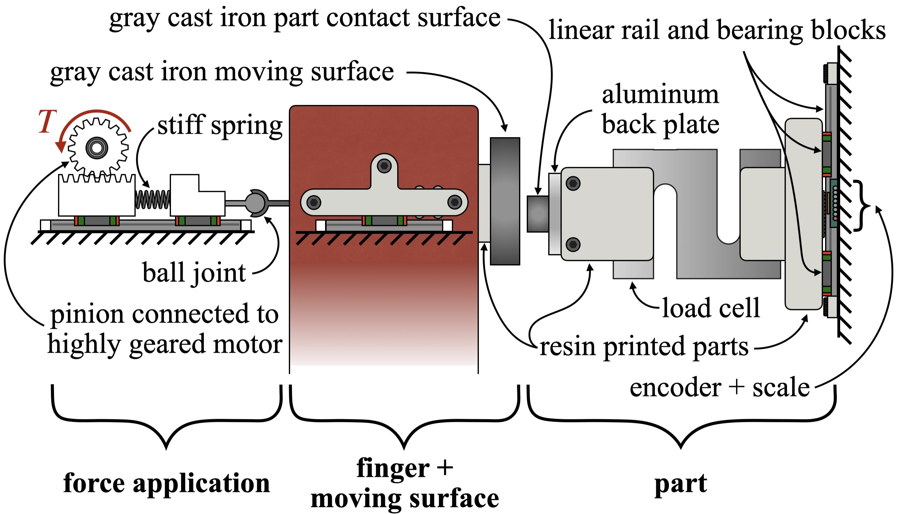
To validate the two above trends, we built a single-finger test setup and transported a gray cast iron part against gravity across a range of waveform parameters and normal forces. The finger is constrained to move linearly by low-friction bearing blocks and rails on either side, a highly geared DC motor pushes the moving surface into the part through a stiff spring and ball joint to apply a prescribed normal force, and the part assembly — gray cast iron contact surface, aluminum backplate, load cell, and resin-printed stiffening components — is constrained to move vertically along a rail with position recorded by a non-contact encoder.
The moving surface was gray cast iron (same material as the part), selected for its high reported static coefficient of friction. Our measured values were $\mu_s = 0.44 \pm 0.04$ and $\mu_k = 0.34 \pm 0.03$ — notably different from the textbook values of $\mu_s = 1.10$ and $\mu_k = 0.15$, which we traced back to 19th-century hand-scraped surfaces and 1940s lathed cast iron respectively.
Sample Data
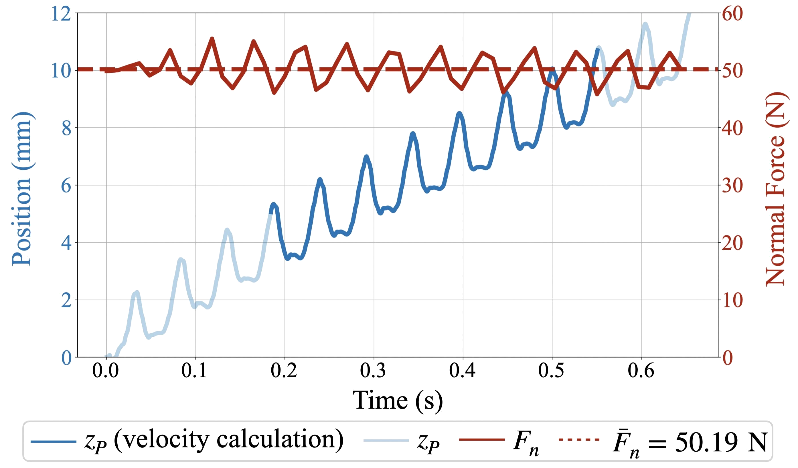
A representative trial (Experiment 3, $F_n$ = 50 N) is shown below. Part position $z_P$ (blue, with the darkened region used for $v_{avg}$ calculation) climbs in a characteristic staircase pattern as sticking phases carry it upward, with small drops during each slip. The normal force $F_n$ (red) oscillates around the 50 N target due to bending in the load cell from the periodic surface vibrations, with the average $\bar{F}_n$ shown as a dashed line. Average velocity is calculated from the slope over the range where the contact area is fully within the moving surface’s bearing.
Effect of $a_{max}$
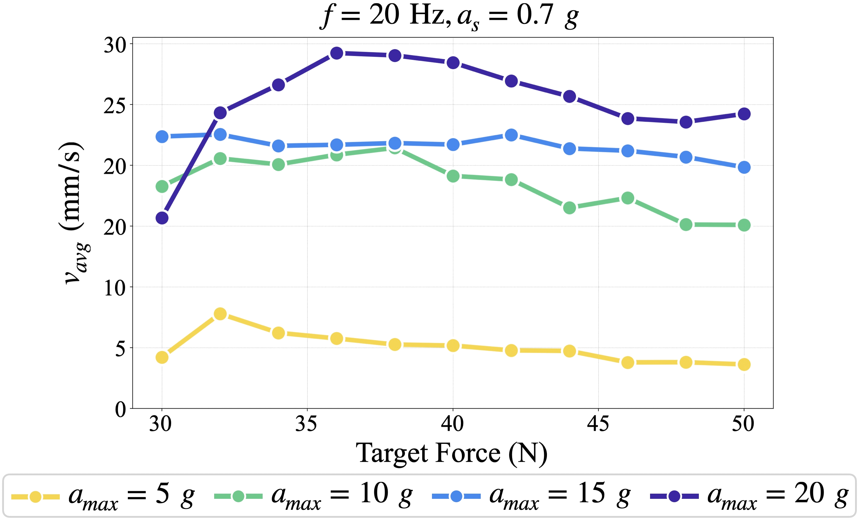
Experiments 1–4 fixed $f$ = 20 Hz and $a_s$ = 0.7$g$ and varied $a_{max}$ from 5$g$ to 20$g$ across 11 normal force values from 30–50 N. Higher $a_{max}$ generally produced higher average part velocity, consistent with the model. The exception was at the lowest normal forces, particularly for $a_{max} = 20g$, where we believe structural vibrations at high accelerations worsened plane-on-plane contact between the moving surface and the part, reducing effective friction. The expected trend becomes more clearly visible at higher normal forces where plane-on-plane contact is better enforced.
Effect of $a_s$
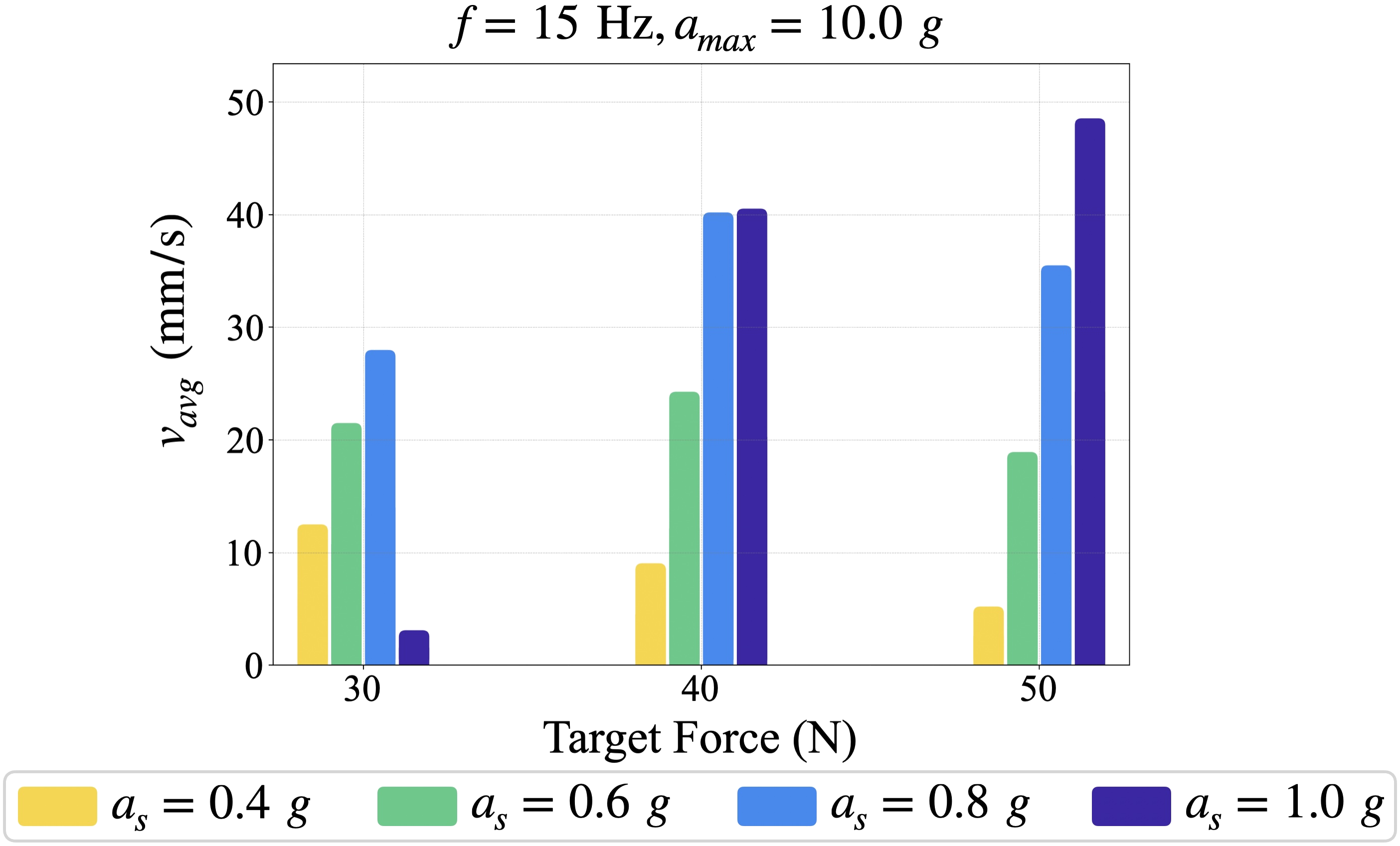
Experiments 5–8 fixed $f$ = 15 Hz and $a_{max}$ = 10$g$ and varied $a_s$ from 0.4$g$ to 1.0$g$ at three normal force values (30, 40, and 50 N). Higher sticking accelerations consistently produced higher average part velocities, again matching the model. The exception was at 30 N for $a_s = 1.0g$, where the increased surface momentum led to greater out-of-plane motion of the cantilevered moving surface, reducing the effective contact area.