Implementation
This section discusses the key mechanical and electrical components of the build, as well as the software used to drive the voice coil actuator (VCA). Note that the same electronics and software used to control the vibrational transmission is used to control the vibrating surface in the vibrating spatula design here.
Mechanical
The full CAD (zipped .step file) can be downloaded by clicking here. The design was created in OnShape, and if the .step file is imported to OnShape a part studio should automatically be created. An interactive visualization of the CAD is provided below.
The single actuator is a LA18-18-000A VCA that consists of a fixed permanent magnet assembly and a moving coil. The moving coil is attached—using 3D-printed parts—to a low-friction (i.e., very-light preload) Hiwin bearing block that slides on a linear rail. Most custom parts were 3D-printed in either PLA Basic on a Bambu Lab X1E or Prusament PLA on a Prusa MK3S+, and the clear base plate on which these parts are mounted is laser cut from 1/4” acrylic. Two different steel spatula blades were used: a 1 mm thick version and an approximately 2 mm thick version (discussed below). The 1 mm thick blade was taken from an icing spatula purchased off of Amazon. The 2 mm thick blade was laser cut in the same profile by SendCutSend in A36 mild steel. A 1/64” thick sheet of neoprene with a sticky backing was fixed to one side of the spatula blade. Hardware includes a mix of M2, M3, and M6 screws, hex nuts, heat set inserts, washers, and split lockwashers, as well as 2 mm, 3 mm, and 1/8” diameter dowel pins for alignment. The magnet assembly is secured using two 10/32 UNF screws.
Note: You will need to adjust the hole sizes / tolerances to match your laser cutter and 3D printer. Please view the full CAD assembly to see which holes are close-fit or press-fit. It’s recommended to undersize the holes and then drill them out on a drill press.
A full bill of materials is provided below.
Manufactured Components
| Manufactured Component | Quantity | Material | Process |
|---|---|---|---|
| Clamp bottom | 1 | PLA | 3D-printing (0.08 mm layer height “High Quality” on X1E) |
| Clamp top | 1 | PLA (resin is ideal) | 3D-printing (0.08 mm layer height “High Quality” on X1E) |
| Bearing block end stops | 1 | PLA | 3D-printing (0.2 mm layer height) |
| Handle | 1 | PLA | 3D-printing (0.2 mm layer height) |
| Input holder bottom | 1 | PLA | 3D-printing (0.2 mm layer height) |
| Input holder top | 1 | PLA | 3D-printing (0.2 mm layer height) |
| Handle | 1 | PLA | 3D-printing (0.2 mm layer height) |
| Magnet assembly mounting bracket | 1 | PLA (resin is ideal) | 3D-printing (0.2 mm layer height) |
| Electronics cover | 1 | PLA | 3D-printing (0.2 mm layer height) |
| Base plate | 1 | 6 mm acrylic | Laser cutting |
| Spatula blade (2 mm) | 1 | 0.074” A36 steel | Laser cutting (by SendCutSend) |
Note: the clamp bottom and top pieces are printed with a 0.08 mm layer height. The clamp bottom contains features that form the partial negative of the bearing block, which is necessary to square up these parts since the bearing block does not contain any press-fit holes for dowel pins; these features are best printed in high resolution.. The clamp top contains a small cutout for the scale portion of the linear encoder, and must be printed with high resolution as well.
Also, note that the coil and magnet can get very hot, to the point where the PLA can deform from the heat. It’s best to print these parts in a higher temp material (White V5 on the Form 4 worked in later devices that used this same actuator).
Hardware Components
| Hardware Component | Quantity | Description |
|---|---|---|
| Voice coil actuator (LA18-18-000A) | 1 | [BEI Kimco] Peak accelerations up to 100 gs |
| Bearing block (MGN07CZ0H) | 1 | [Hiwin] Very-low preload for minimal friction, attached to moving coil |
| Linear rail (MGNR07R) | 1 | [Hiwin] Linear rail on which the bearing block slides |
| 1/64” thick neoprene | 1 | High-friction surface on the output surface |
| 10/32 x 5/8” UNF socket head screw | 2 | Secures magnet assembly to its mounting bracket |
| 10/32 split lockwasher | 2 | Prevents unscrewing of magnet assembly screws |
| 10/32 washer | 2 | Distributes load from lockwasher |
| M2 x 8 mm flathead screw | 4 | Secures encoder to base plate |
| M2 x 8 mm socket head screw | 8 | Secures rail to base plate, and motor driver to electronics cover |
| M2 x 14 mm socket head screw | 4 | Secures clamp top and bottom to the bearing block |
| M2 split lockwasher | 4 | Prevents unscrewing of clamp to bearing block screws |
| M2 washer | 4 | Distributes load from lockwasher |
| M3 x 10 mm socket head screw | 2 | Clamps clamp top and clamp bottom around the spatula blade |
| M3 x 12 mm socket head screw | 2 | Secures moving coil to clamp top |
| M3 x 25 mm socket head screw | 4 | Secures handle to the base plate, and the input holder top to the input holder bottom |
| M3 x 35 mm socket head screw | 2 | Secures input holder bottom to the base plate |
| M3 split lockwasher | 2 | Prevents unscrewing of moving coil screws |
| M3 washer | 2 | Distributes load from lockwasher |
| M3 hex nut | 6 | Secures input holder top and bottom, input holder bottom to base plate, and clamp top and bottom |
| M6 x 16 mm socket head screw | 4 | Secures the magnet assembly mounting bracket to the base plate |
| M2 heat set insert | 11 | Inserted into base plate to secure encoder and linear rail |
| M3 heat set insert | 2 | Inserted into handle to secure it to the base plate |
| M6 heat set insert | 4 | Inserted into base plate to secure magnet assembly mounting bracket |
| 1/8” x 1/2” dowel pin | 2 | Used to center the magnet assembly and moving coil |
| 2 mm x 10 mm dowel pin | 2 | Aligns the clamp top and clamp bottom |
| 3 mm x 12 mm dowel pin | 2 | Aligns spatula blade to the 3D-printed clamp (top and bottom) |
| 3 mm x 16 mm dowel pin | 2 | Align magnet assembly mounting bracket to the base plate |
Electrical
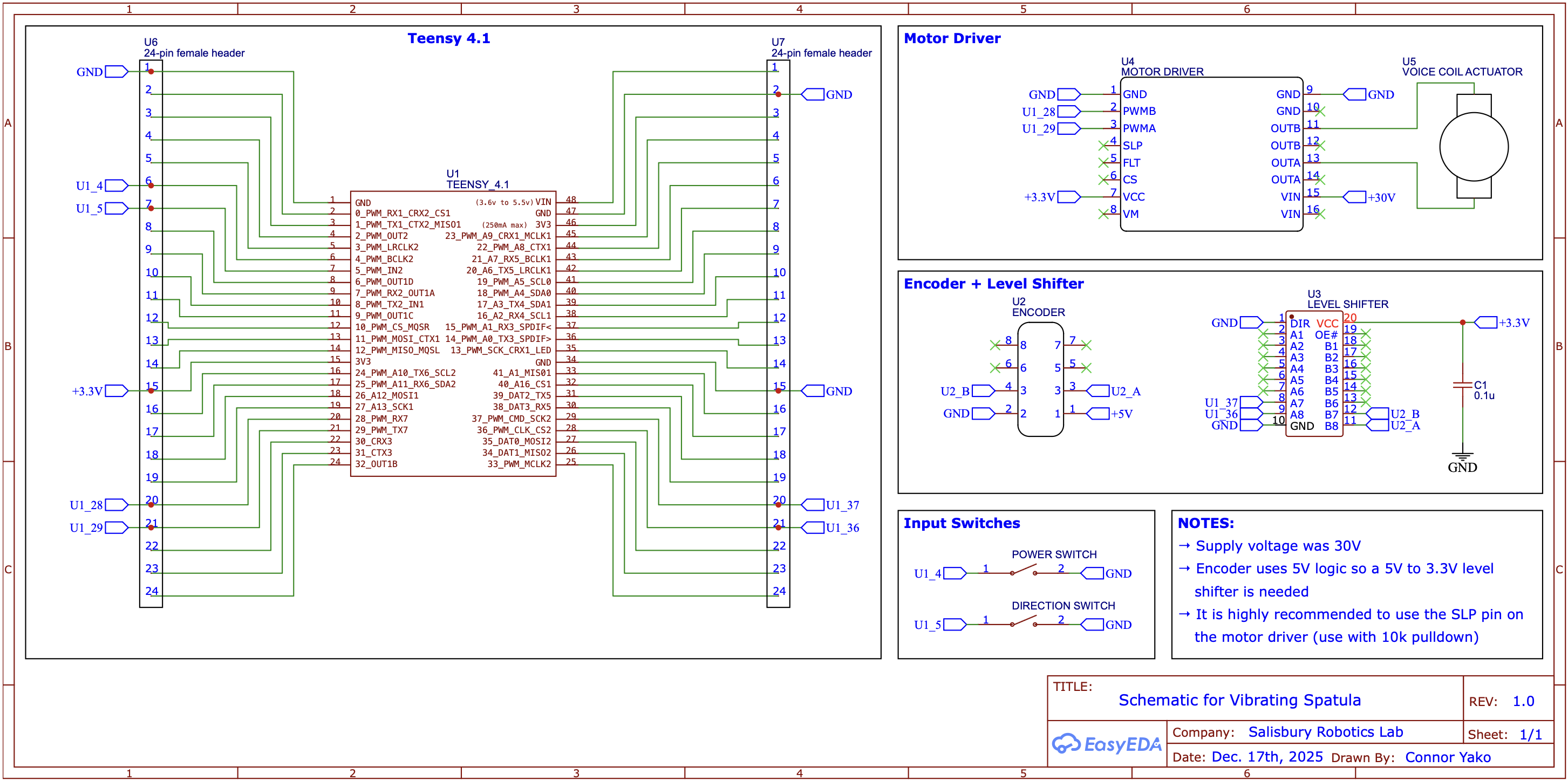
The spatula is driven by the LA18-18-000A VCA from BEI Kimco. To power the motor we use the H2 motor driver from Pololu. The motor driver was supplied with 30 V from a variable benchtop power supply (Mastech HY3005F-3), and can deliver 11 A of continuous current. The driver can support up to 60 V (with a recommended maximum of 48 V)—these higher supply voltages can help deal with the inductive spikes caused by the quickly changing desired accelerations required by the Quaid waveform, and are recommended if you have a powerful enough supply. The spatula position is controlled by a simple PD controller running at 40 kHz, with position feedback provided by a high resolution encoder from Posic. The encoder outputs A/B pulses at 1 MHz with a resolution of 5 µm, though different resolutions can be programmed depending on the expected maximum velocity.
There are also two rocker switches and four potentiometers in the design. Initially, the potentiometers were used to play around with various waveform parameters and PD gains, however, the analog reads were a bottleneck in the high-speed control loop and impacted the position tracking. Therefore, they were not used in the final build. The rocker switches were used to control the power state (on / off) and the transport direction (toward / away from the user) and the power state (on / off).
A Teensy 4.1 was used as the microcontroller. The A / B channels of the encoder were connected to pins 36 and 37 on the Teensy, as these are hardware quadrature encoder channels. The two PWM pins for controlling the motor driver were connected to pins 28 and 29 on the Teensy (which use FlexPWM timers).
Schematic
The full circuit schematic is shown below and available as a PDF here.
A table of the components used is below.
Electrical Components
| Electrical Component | Quantity | Description |
|---|---|---|
| Teensy 4.1 | 1 | Microcontroller |
| Pololu H2 motor driver | 1 | PWM-based motor driver for powering the VCA |
| Posic linear encoder + scale | 1 | Non-contact encoder (ID1102L) and scale (TPLS04-026) |
| Rocker switch (SPST) | 2 | Controlling device on / off and transport direction |
| Level shifter (SN74LVC245A) | 1 | Shift 5V encoder signal to 3.3V for Teensy |
| Capacitor 0.1u | 1 | Bypass capacitor for the level shifter |
Software
There are two main software components: the Teensy code and the Python code. The Teensy code is for running vibrating spatula. The Python code is used for pre-selecting the waveform parameters with which the spatula vibrates, as well as realtime plotting for tuning the PD gains. Everything is available on GitHub.
The high-level function of the Teensy code is to have the spatula track a user-defined quadratic position waveform, known as the Quaid waveform. The Quaid waveform is specified in the file QuaidWaveformSelector.h, which has the below structure:
// #define FREQ_20_HZ
#define FREQ_30_HZ
// #define FREQ_40_HZ

#if defined(FREQ_20_HZ)
float quaid_frequency = 20;        // Hz
float min_acceleration_gs = 0.25;  // gs
float max_acceleration_gs = 50.0;  // gs

#elif defined(FREQ_30_HZ)
float quaid_frequency = 30; // Hz
float min_acceleration_gs = 2.25;  // gs
float max_acceleration_gs = 50.0;  // gs

#elif defined(FREQ_40_HZ)
float quaid_frequency = 40;        // Hz
float min_acceleration_gs = 3.0;   // gs
float max_acceleration_gs = 50.0;  // gs
Select the desired vibration waveform frequency by uncommenting the corresponding #define at the top of the file, which in the above example is 30 Hz. The rest of the waveform is defined by the two acceleration variables, min_acceleration_gs and max_acceleration_gs. These values can be a bit abstract, so there is a Python helper function, quaid_waveform_visualizer.py, that allows you to visualize the waveform based on the parameters you select. This can help ensure that the tracked waveform amplitude is less than the actuator stroke, as shown below, where the maximum stroke is set to 6 mm.

Once the desired vibration waveform has been selected, the next thing to do is ensure that the spatula is actually tracking this position waveform. The PD controller gains can be changed by using the controller.set_gains() in void setup() of main.cpp as shown below.
// default kp and kd values shown, but these will differ based on your system
float kp = 4000;
float kd = 6;
controller.set_gains(kp, kd);
Note: the default kp and kd values are quite aggressive, and are needed to track the sharp peaks present in the position waveform when max_acceleration_gs is large (larger leads to faster transport velocities); these values of kp and kd will most likely lead to instability for tracking a single target position, rather than the rapidly changing position waveform in this work.
As part of the control loop, the desired and target positions are sent at 1 kHz to a Python program, realtime_plotter.py. By uploading the code to the Teensy 4.1 (and making sure that #define RUN is uncommented in main.cpp), and then running this Python program the tracking performance of the defined PD controller can be visualized.
First Time Operation
Always try lower gains, lower frequencies, and smaller waveform amplitudes when first starting out with the device. You should also confirm the encoder readings before trying out the controller (see the function encoder.print_position_change() in main.cpp). Also:
![]() WEAR HEARING PROTECTION!
WEAR HEARING PROTECTION!
The device can be loud, especially with more aggressive waveforms (higher max accelerations and larger amplitudes) because of the resonating parts. If you need any help at all getting things up and running please reach out to clyej3@gmail.com and I am more than happy to work with you.