Implementation
This section discusses both the implementation of the physical gripper seen on the overview page, but also the MATLAB code used to simulate part motion in response to optimal surface motion and to compare observed part motion with simulated part motion.
Mechanical
The full CAD (zipped .step file) can be downloaded by clicking here. The design was created in OnShape, and if the .step file is imported to OnShape a part studio should automatically be created. An interactive visualization of the CAD is provided below.
All custom parts were either laser cut out of 3/16” birch plywood or 3D-printed on a Prusa MK3S+ with Prusament PLA in Galaxy Black. The laser cut parts were aligned with 2 mm dowel pins and secured with M3 socket head screws that threaded into undersized holes. The pin joints of the parallelogram mechanism were created with 6 mm shoulder bolts with M5 threads that also screwed into undersized holes in the plywood. M6 washers were used as low-cost thrust bearings between the moving links of the mechanism. The 3D-printed parts are secured with a mix of undersized holes and washers.
Note: You will need to adjust the hole sizes / tolerances to match your laser cutter and 3D printer. Please view the full CAD assembly to see which holes are undersized (for threading), close-fit, or press-fit.
A full bill of materials is provided below.
Manufactured Components
| Manufactured Component | Quantity | Material | Process |
|---|---|---|---|
| Non-geared link | 8 | 3/16” birch plywood | Laser cutting |
| Geared link | 4 | 3/16” birch plywood | Laser cutting |
| Geared link (drive) | 4 | 3/16” birch plywood | Laser cutting |
| Handle | 2 | 3/16” birch plywood | Laser cutting |
| Flexure base connection | 4 | 3/16” birch plywood | Laser cutting |
| Knob | 1 | PLA | 3D-printing (0.2 mm layer height) |
| Flexure base | 2 | PLA | 3D-printing (0.2 mm layer height) |
| Flexure | 4 | PLA | 3D-printing (0.1 mm layer height) |
| Rigid platform | 2 | PLA | 3D-printing (0.2 mm layer height) |
| Motor holder | 2 | PLA | 3D-printing (0.2 mm layer height) |
Most of the below hardware components were either found around the lab or can be ordered from McMaster-Carr.
Hardware Components
| Hardware Component | Quantity | Description |
|---|---|---|
| Carlton haptic actuator | 2 | (Nanoport Technology) generates large, impact induced accelerations |
| 40A neoprene sheet, 12” x 12”, with crisscross texture | 1 | (McMaster-Carr) Adhesive back, used as the high-friction surface |
| M2 x 6 mm socket head screw | 8 | Secure motor and motor holder to moving surface |
| M2 x 4 mm socket head screw | 8 | Connect flexures to moving surface |
| M2.5 x 8 mm socket head screw | 8 | Connect flexures to their 3D-printed base |
| M2.5 hex nut | 8 | Connect flexures to their 3D-printed base |
| M3 x 8 mm socket head screw | 28 | Hold doubled-up plywood parts together |
| M3 x 25 mm socket head screw | 4 | Connect 3D-printed input knob to parallelogram mechanism input |
| M5 x 25 mm shoulder bolt (shoulder diameter is 6 mm) | 8 | Act as joints in the parallelogram mechanism |
| M6 x 12 mm shoulder bolt (shoulder diameter is 6 mm) | 6 | Connect parallelogram mechanism to 3D-printed flexure base |
| M6 washer (1.8 mm thick) | 16 | Act as low-cost thrust bearings |
| M6 hex nut | 6 | Connect parallelogram mechanism to 3D-printed flexure base |
| 2 mm x 8 mm long dowel pin | 48 | Align doubled-up plywood parts |
Electrical
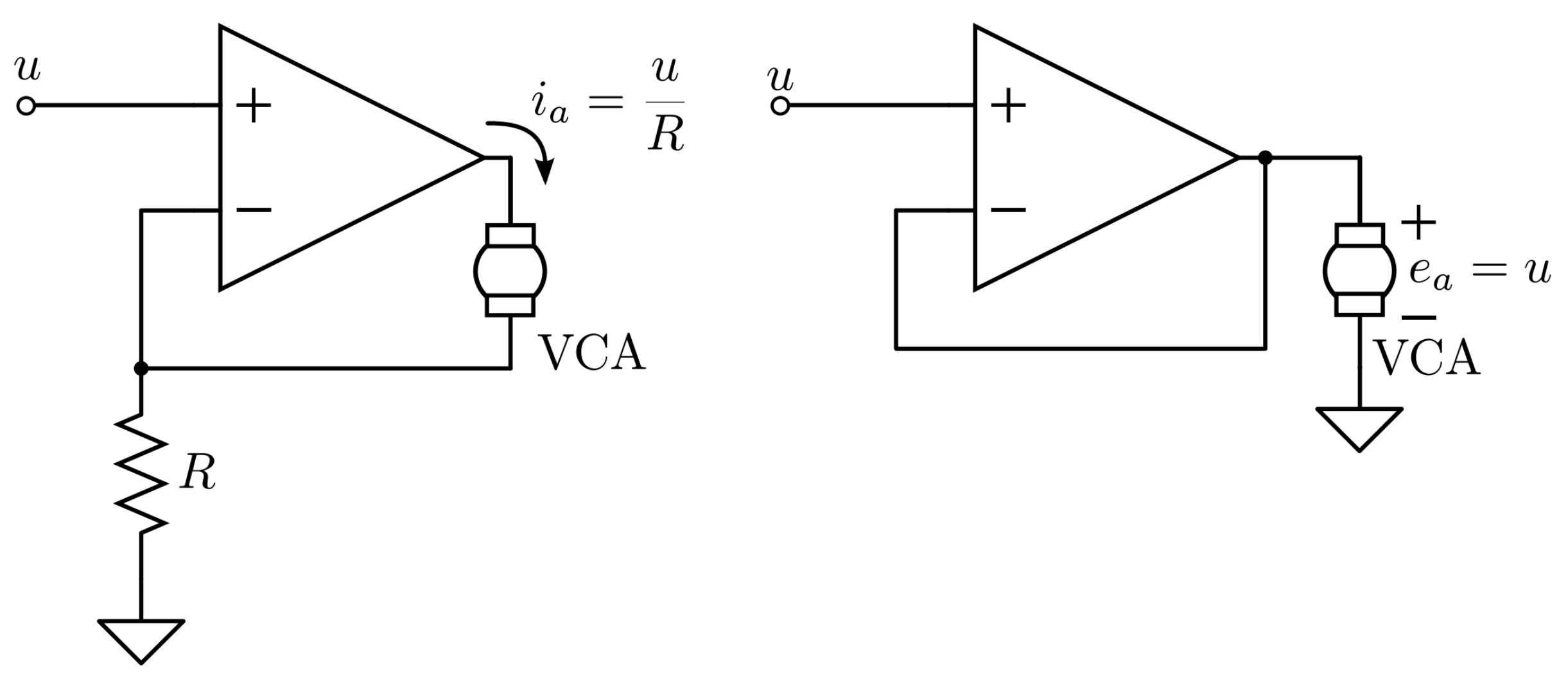
The moving surfaces are driven by Carlton Haptic Actuators, a type of voice coil actuator. Since the generated force is proportional to the current through the coil, it is preferable to control the motor’s current rather than the voltage across its terminals. To do this, we used the current-drive circuit described by McMahan and Kuchenbecker (McMahan 2014) , and shown on the left side below.
Schematic
The full circuit schematic is shown below and available as a PDF here.
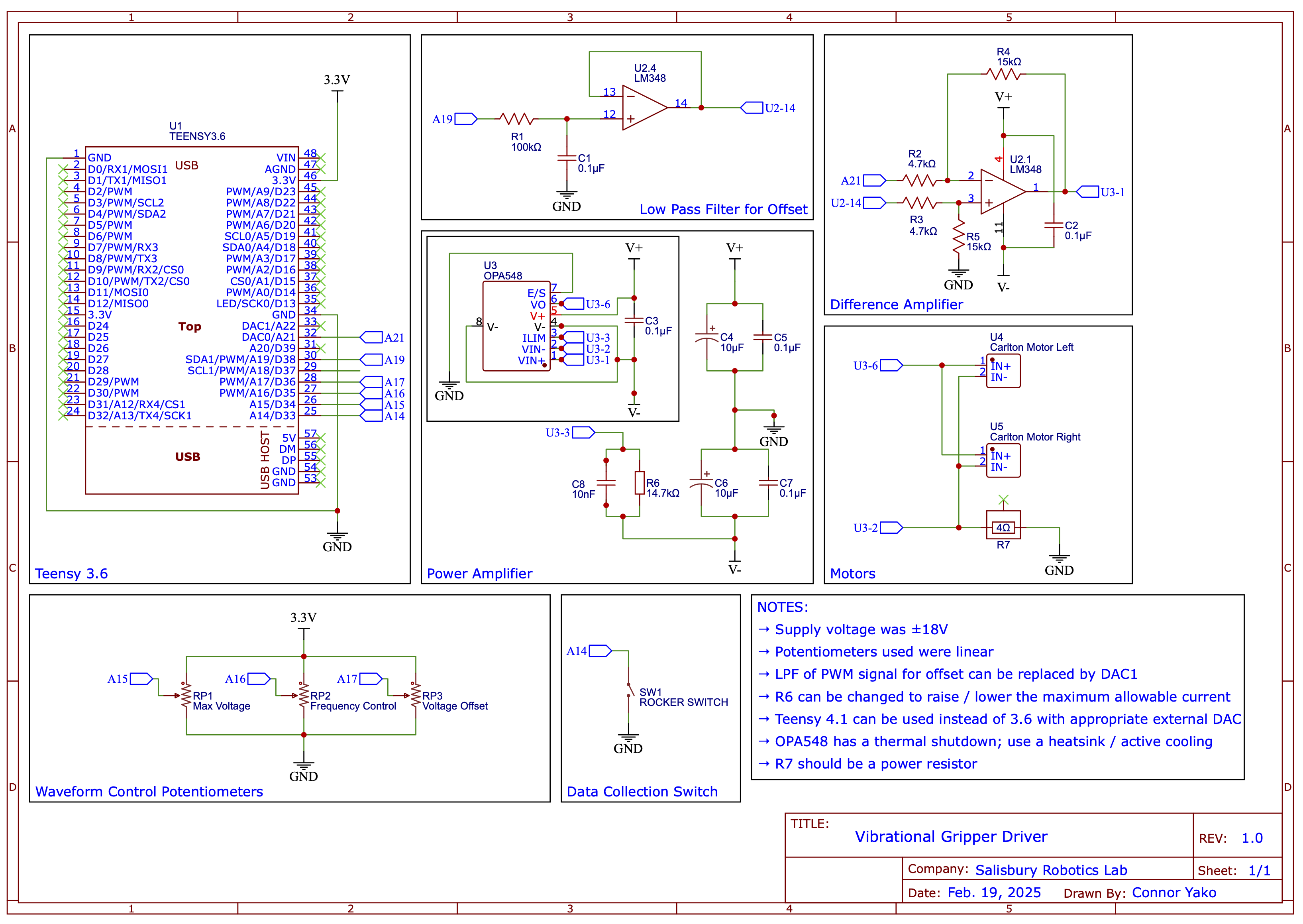
![]() The above circuit schematic assumes equal motor parameters to ensure the same current flows through both motors. Since this is likely not the case, separate OPA548 power amps and power resistors should be used with each motor.
The above circuit schematic assumes equal motor parameters to ensure the same current flows through both motors. Since this is likely not the case, separate OPA548 power amps and power resistors should be used with each motor.
We used a 300 W benchtop power supply (Mastech HY3005F-3) with the two controllable outputs set to series-mode to achieve a dual supply capable of ±30 V (only used it at ±18 V) and 5 A. The schematic also shows the use of a Teensy 3.6, which was used for its built-in DAC, however, these are difficult to come by. Instead, a Teensy 4.1 can be used with an appropriate external DAC (such as the MCP4922, which has an SPI interface, or something faster that uses I2S).
![]() Running the device at too high of currents for extended periods of time can cause the yellow plastic housing of the actuator to melt. Select R6 to set the desired current limit output of the OPA548 power amp (see the table in Fig. 41 in the OPA548 datasheet), and ensure the power resistor, R7, is sufficient based on your desired current limit.
Running the device at too high of currents for extended periods of time can cause the yellow plastic housing of the actuator to melt. Select R6 to set the desired current limit output of the OPA548 power amp (see the table in Fig. 41 in the OPA548 datasheet), and ensure the power resistor, R7, is sufficient based on your desired current limit.
Software
The code is broken up by usage: the Teensy code is for running the gripper, and the MATLAB code is for running simulations using the dynamical model and visualizing experimentally obtained data. Everything is available on GitHub.
Teensy
The Teensy code has several functions:
- Read a rocker switch that determines if the device is on / off.
- Send a sawtooth current waveform to the actuators.
- Adjust the sawtooth current waveform based on user-controlled potentiometer inputs.
The code can be found in teensy/ on GitHub.
![]() The Teensy code has been cleaned up without retesting on the gripper, as it is no longer in service. Please use caution when running the gripper for the first time (try running at lower currents, use a scope to check the output current waveform across the power resistor), and if you need any help getting things up and running please send an email to clyej3@gmail.com.
The Teensy code has been cleaned up without retesting on the gripper, as it is no longer in service. Please use caution when running the gripper for the first time (try running at lower currents, use a scope to check the output current waveform across the power resistor), and if you need any help getting things up and running please send an email to clyej3@gmail.com.
MATLAB
The MATLAB code has three .m files and two .slx (Simulink) files. You should not need to worry about the file stick_slip.m, as this is used by both Simulink files to calculate the friction force in the simulations. There is also a data/ folder that contains 10 experimental trials, where surface and part motion were recorded. This data can be used across the rest of the .m and .slx files. For these files:
-
experimental_vs_optimal_comparison.mshould be used withvibrational_transport_optimal_surface.slx. As part of the paper, we determined what the optimal surface motion should be in a given situation to maximize the average part velocity. Runexperimental_vs_optimal_comparison.mand then view the results invibrational_transport_optimal_surface.slx, using the scopes to compare simulated part motion in response to optimal surface motion with the experimentally observed part motion. Set various parameters such as the part mass and friction coefficients in Section C, as well as the parameters of the optimal surface motion (such as the frequency,freqand the maximum acceleration,a_max) in Section D. -
parameter_estimation.mshould be used witihvibrational_transport_experimental_surface.slx. These files have two main functions. First, you can fit the normal force, $F_n$, for each individual trial and the kinetic coefficient of friction, $\mu_k$ across all trials, to try and get the best fit between the experimentally observed part motion and the simulated part motion (Section C). Second, you can compare the fit for individual trials by selecting a specific trial in Section E. You can play around with the normal force and kinetic coefficient of friction by putting your own values in theparamsarray.
The code can be found in matlab/ on GitHub.
Getting Things Up and Running
As noted above, the Teensy code has been cleaned up without retesting on the gripper, as it is no longer in service. Please use caution when running the gripper for the first time (try running at lower currents, use a scope to check the output current waveform across the power resistor). Also, please be sure to:
![]() WEAR HEARING PROTECTION!
WEAR HEARING PROTECTION!
The device is incredibly loud. If you need any help at all getting things up and running please reach out to clyej3@gmail.com and I am more than happy to work with you.